All devices are toys. So, I played.
Here is a picture of the kind of waveform I would suppose you want to see from this device.
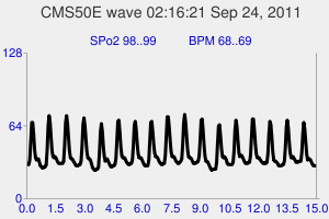
Fine, fine.
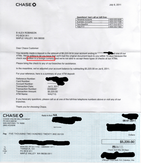
Now, let’s start with the first thing that made no sense.
Starting at, say, 96% SPo2 and doing a breath-out-hold, the SPo2 level goes up! Ditto, for the whole duration of a big-breath-in, breath-hold. The device’s 30 second lag confuses things. You stop holding your breath and start breathing – the SPo2 level goes down! Well, it’s just then reporting on the old, breath-hold blood.
Big-breath-in hold is peculiar. The SPo2 level never really goes down, but the pulse rate can go from 60 to 80+. It appears that my body, if not yours, compensates for no air by simply beating the heart faster.
Which brings up the really wild thing that this device showed about my body.
Here’s the deal:
After racing around Lake Sacajawea late one night with Strom a couple months before going in to the service, I had some ice cream and hit the sack. Soon, my chest felt very uncomfortable. It was plain that my heart had stopped beating. This can be disconcerting to an 18 year old. I felt my pulse. Nothing. It lasted several seconds at least. Who knows. Time passes slowly when you think your heart’s gone south. Two lessons learned:
- Don’t eat ice cream before bed.
- If your heart stops, sit up.
Of course, I wasn’t about to tell anyone about it. In fact, I pretty much forgot about it – but did remember the two lessons.
Years later, Scott’s just born. Imani is at the hospital. I’m home and going to sleep. Maybe I had ice cream. Dumb, sure, but hey, the lessons may have slipped my mind under the circumstances. Anyway, guess what. Yeah. I sat up to fix the problem. Bit of a scare.
Years later, I hooked up a heart monitor on the chance of seeing some indication of what was going on. Nothing. Still have a textbook-clean, ECG from Physio in a drawer somewhere.
Now, here’s the other half of the deal:
Some time recently when going to sleep, I noticed a half feeling like the heart-stop thing. Not dramatic, but not normal. This has been going on for some time, but it had never really bubbled up to daytime notice.
So, what does this CMS50E pulse oximeter display? A graph of heartbeat action. And it beeps when it senses a peak – at beat time – matching wrist-pulse and general senses perfectly.
The other day, I was up at Mark M’s and got him to try the device. Maybe the device was bad. The SPo2 level didn’t drop below 94%, after all. But, on Mark, the device worked just dandy – the SPo2 number went down as one would expect, though delayed a few seconds.
So, now what?
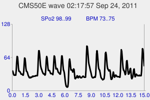
I put the device on me and turned on heart beat beeping. Mark’s like: “What’s with that?!” The beeping could have been a random number generator. Not all the time. But some times. No logic to it, though I suspect that things even out as soon as I do something other than sit still. Anyway, I’d already seen it for hours the night before. Several seconds, no beat. 5 steady beats, miss a beat, 5 steady beats, miss a beat. Couple weak beats. Etc. Random. Weird.
So … interesting. I’ll take the device for a walk as soon as it appears that the “kidney stone” can take shaking. (Postscript: Yes, erratic all the way around Maplewood.)
Here’s a waveform without much flatlining:
And, that’s not the only oddity.
How to get a solid 99% SPo2 instead of a wimpy 97% or 98%? Just sit there bouncing a leg on the toes.
And:
Speaking of toes. The device works on toes as well as fingers. That’s nice, since you can’t type with the device on a finger. Coding tz_cms50.py involved a lot of un-clip/clipping.
So, what about the code?
Another post, is what.